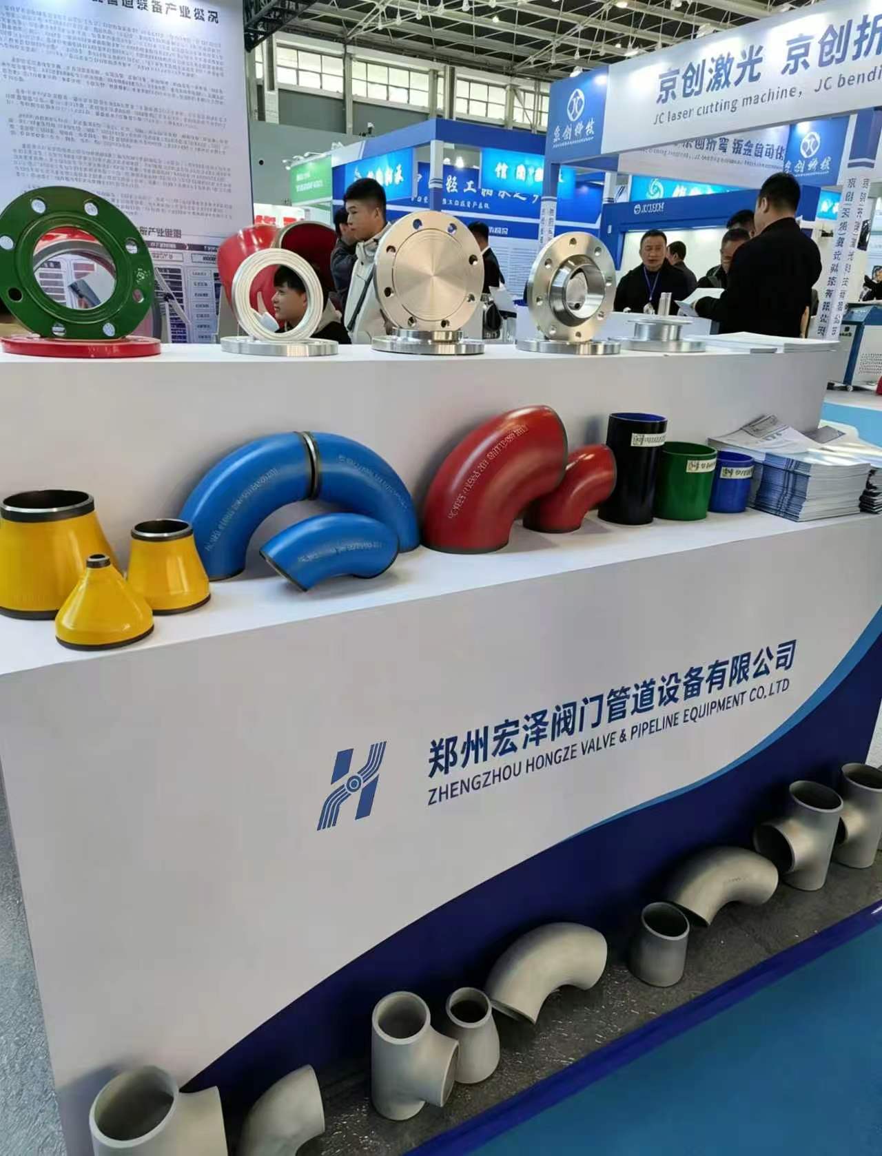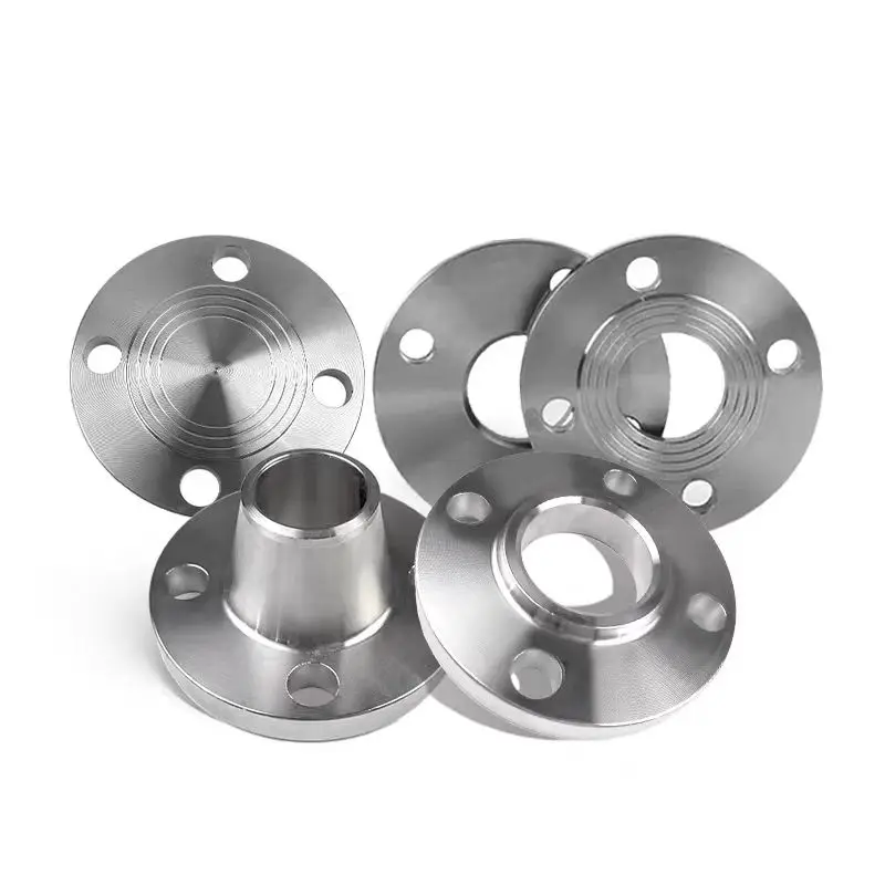
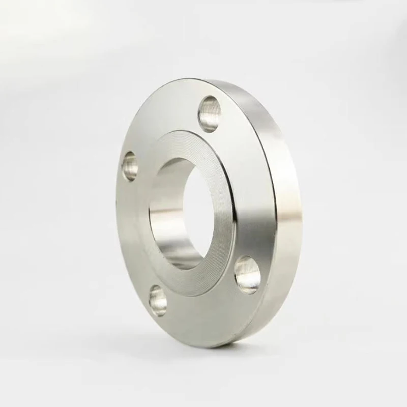
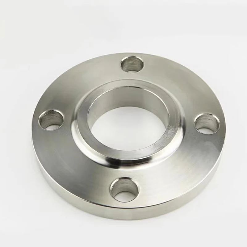

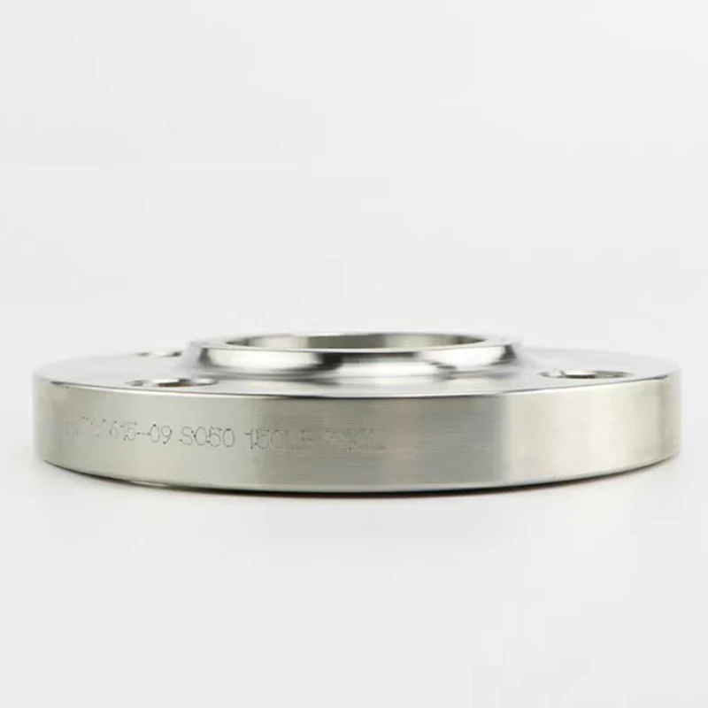
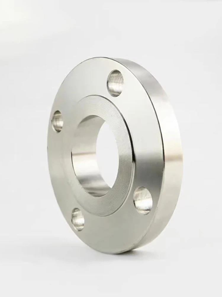
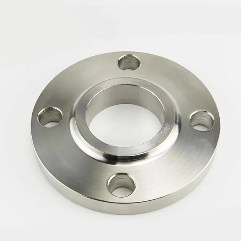
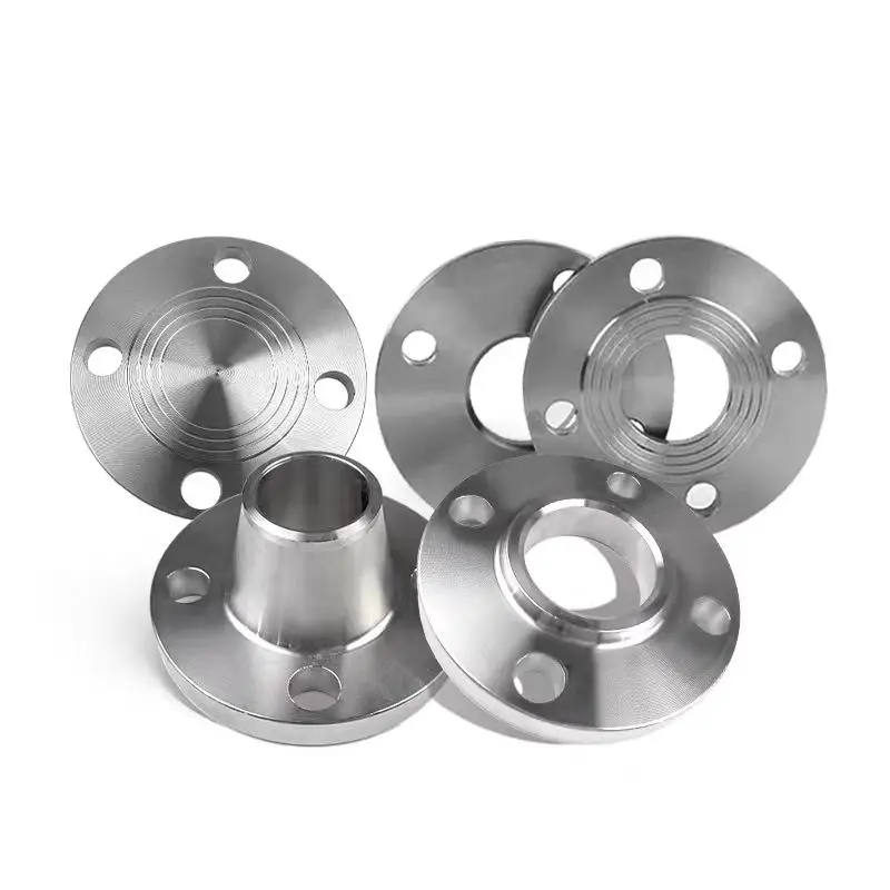
Industrial Pipe Flanges for Pipeline, Valve and Equipment Connections
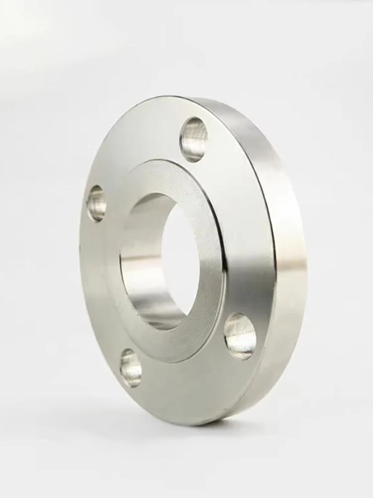
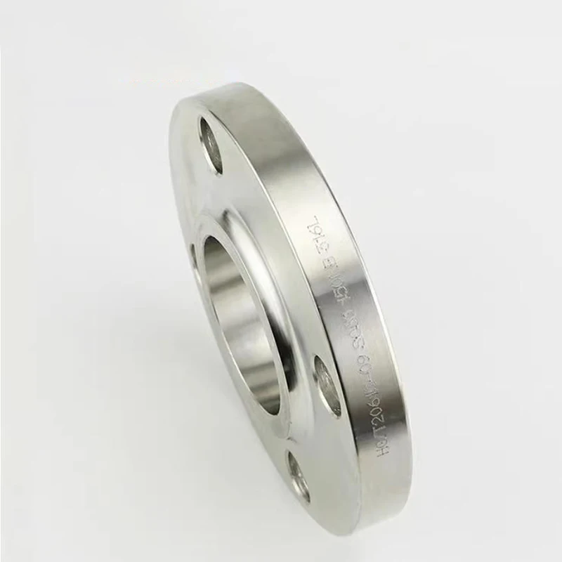
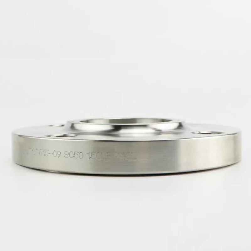
Hongze industrial pipe flanges provide detachable, bolted connections between pipes, valves, pumps, pressure equipment and other piping components. Each flange is selected as part of a complete joint that includes a compatible mating flange, gasket, bolting, pipe or nozzle, pressure-temperature rating and installation procedure.
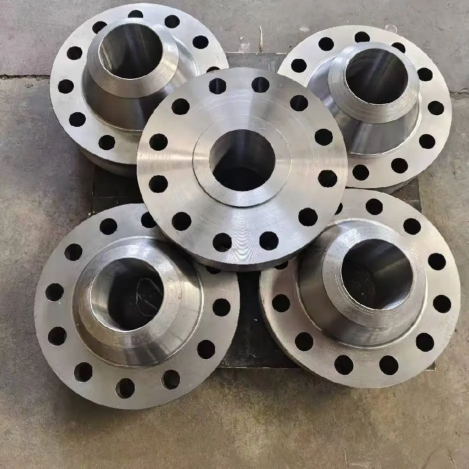
Zhengzhou Hongze Valve Pipeline Co., Ltd. supplies slip-on flanges, weld neck flanges, blind flanges, plate flanges, socket weld flanges, threaded flanges, lap joint flanges, high-pressure forged flanges and custom large-diameter flanges. Carbon steel, low-temperature carbon steel, stainless steel, alloy steel, duplex stainless steel and drawing-specific materials are available for water, steam, oil and gas, petrochemical, power, marine, HVAC and industrial process piping.
Standard and custom production can be evaluated according to ASME B16.5, ASME B16.47 Series A or Series B, EN 1092-1, JIS B 2220, GB/T 9124, HG/T, AWWA C207 and project drawings. Because flange dimensions and pressure-temperature ratings depend on the exact standard, material group, size, class or PN, facing and flange type, the complete designation must be confirmed before quotation and manufacturing.
Key Product Capabilities
- Standard forged and plate flange types for general and demanding industrial piping.
- ASME Class 150, 300, 400, 600, 900, 1500 and applicable Class 2500 products.
- EN and GB PN-designated flanges from low-pressure services to project-specified high-pressure classes.
- JIS 5K, 10K, 16K, 20K, 30K, 40K and 63K options where applicable.
- Carbon steel, stainless steel, alloy steel, low-temperature steel and duplex grades.
- RF, FF, RTJ, tongue-and-groove, male-and-female and drawing-specific facings.
- Large-diameter flanges according to ASME B16.47, EN 1092-1, AWWA C207 or approved drawings.
- Custom bore, outside diameter, thickness, bolt circle, drilling, hub, facing and welding-end preparation.
- Non-standard replacement flanges manufactured from drawings, samples or verified site dimensions.
- Optional PMI, UT, MT, PT, impact testing, hardness testing and material documentation.
- Custom marking, coating, rust protection, seaworthy packing and export documents.
General Flange Specification Options
| Parameter | Available Range or Option |
|---|---|
| Product | Industrial Pipe Flange / Steel Pipe Flange / Custom Flange |
| Flange types | Weld neck, slip-on, blind, plate, socket weld, threaded, lap joint, reducing, orifice and drawing-specific flange |
| Nominal size | NPS 1/2-NPS 60 within applicable ASME standards; larger waterworks and EN sizes; other sizes according to engineering review |
| ASME pressure classes | Class 75, 150, 300, 400, 600, 900, 1500 and 2500 where permitted by the selected standard, size and type |
| EN / GB pressure designation | PN 2.5-PN 400 where applicable; availability depends on standard, type, size and material |
| JIS pressure designation | 5K, 10K, 16K, 20K, 30K, 40K and 63K where applicable |
| Common standards | ASME B16.5, ASME B16.47 Series A/B, EN 1092-1, JIS B 2220, GB/T 9124.1, GB/T 9124.2, HG/T and AWWA C207 |
| Materials | Carbon steel, low-temperature carbon steel, stainless steel, alloy steel, duplex stainless steel and approved plate materials |
| Facing | RF, FF, RTJ, TG, MFM or custom machined face |
| Pipe bore / schedule | Standard bore or matched to pipe schedule, wall thickness and welding-end requirement |
| Surface protection | Rust-preventive oil, black paint, zinc-rich paint, hot-dip galvanizing where technically suitable, epoxy system or project coating |
| Marking | Standard, size, class/PN, material grade, heat number, manufacturer mark and project-specific marking |
| Inspection | Visual and dimensional inspection as standard; PMI, UT, MT, PT, impact, hardness and other testing by agreement |
| Documentation | Inspection report, material certificate, test reports, packing list, certificate of origin and project-required documents |
| Customization basis | Applicable standard, customer drawing, mating component drawing, sample or verified dimensions |
Technical note: The ranges above describe supply capability, not one universal flange configuration. Not every combination of flange type, material, nominal size and pressure class is covered by every standard. Final dimensions and pressure-temperature rating must follow the selected standard edition, material group and approved drawing.
Pipe Flange Types and Selection Guide
| Flange Type | Connection | Typical Use | Important Selection Point |
|---|---|---|---|
| Weld Neck Flange (WN) | Butt-welded hub | Higher pressure, temperature cycling and critical process piping | Specify pipe OD, schedule or wall thickness and weld-end preparation |
| Slip-On Flange (SO) | Pipe slips into flange and is fillet welded | General industrial piping where the governing code permits | Confirm bore, insertion position, welding procedure and service severity |
| Blind Flange (BL) | Bolted closure without bore | Closing pipe ends, valve ends and equipment nozzles | Blind thickness and pressure rating are design-critical, especially at large sizes |
| Plate Flange (PL) | Plate ring welded or otherwise connected as specified | Water, HVAC and selected low-to-moderate pressure systems | Plate grade, manufacturing method and use must be permitted by the selected standard or design |
| Socket Weld Flange (SW) | Pipe inserted into socket and fillet welded | Smaller-bore pressure piping | Specify pipe schedule and required root gap; not interchangeable with slip-on |
| Threaded Flange (THD) | Internal pipe thread | Selected small-bore services where welding is undesirable | Specify thread form, schedule, medium, temperature and code restrictions |
| Lap Joint Flange (LJ) | Loose backing flange used with stub end | Systems requiring frequent alignment or disassembly | Flange and stub end must be specified together; verify facing and material combination |
| Reducing Flange | Flanged joint with reduced bore | Direct transition between selected pipe sizes | Check flow, pressure drop, bolt access, bore geometry and standard limitations |
| Orifice Flange | Matched flange pair with pressure-tap arrangement | Flow measurement systems | Provide complete standard, tap type, bore, gasket and instrument requirements |
| Non-Standard Flange | Drawing-specific bolted or welded connection | Equipment replacement, special nozzle, legacy system or unusual project interface | Requires verified dimensions, design basis, pressure/temperature and drawing approval |
International Standards, Sizes and Pressure Designations
| Standard | Published Scope | Typical Designations | Ordering Requirement |
|---|---|---|---|
| ASME B16.5 | NPS 1/2 through NPS 24 | Class 150, 300, 400, 600, 900 and 1500; Class 2500 through NPS 12 | Specify type, NPS, class, material, facing, bore/schedule and standard edition |
| ASME B16.47 | NPS 26 through NPS 60 | Class 75, 150, 300, 400, 600 and 900 | Series A and Series B have different dimensions and are not interchangeable; series is mandatory |
| EN 1092-1 | Steel flanges within a broad DN10-DN4000 standard scope | PN 2.5 to PN 400 within applicable type/size combinations | Specify EN flange type number, DN, PN, material and facing designation |
| JIS B 2220 | Steel pipe flanges from 10A to 1500A within the standard scope | 5K, 10K, 10K thin, 16K, 20K, 30K, 40K and 63K | Specify nominal size, K rating, material, flange type and facing |
| GB/T 9124.1 | Steel pipe flanges, PN-designated series | Applicable PN series | Use the current applicable part, type, PN, DN, material and facing |
| GB/T 9124.2 | Steel pipe flanges, Class-designated series | Applicable Class series | State Class-series standard explicitly; do not describe it only as “GB flange” |
| AWWA C207 | Steel waterworks flanges from 4 in. through 144 in. | Ring-type slip-on and blind flange classes defined by the waterworks standard | Suitable for applicable waterworks service; provide AWWA class, size, pipe OD and project conditions |
| DIN / HG/T / Project Standard | Depends on the exact referenced document | Document-specific | Provide the full standard number, edition and flange designation; “DIN flange” alone is insufficient |
Why there is no single universal dimensional chart: A DN100 PN16 flange, an NPS 4 Class 150 flange and a JIS 10K 100A flange are different products. Even at the same nominal pipe size, outside diameter, thickness, bolt circle, bolt-hole quantity, hole diameter, hub dimensions and facing may differ. Hongze prepares the dimensional drawing from the exact flange designation before non-standard or critical production.
Large-Diameter and Custom Flanges
Hongze supports large-diameter flange projects for pipelines, valves, expansion joints, pressure equipment, waterworks, ducts and special machinery. Standard large-diameter products can be evaluated under ASME B16.47, EN 1092-1, JIS B 2220 and AWWA C207. Sizes outside a published standard or unusual combinations must be treated as engineered, non-standard flanges rather than automatically assigned a standard pressure class.
| Large-Diameter Requirement | Available Approach | Information to Confirm |
|---|---|---|
| NPS 26-NPS 60 process flange | ASME B16.47 Series A or Series B where applicable | NPS, class, series, type, material, facing and bore/wall thickness |
| DN700-DN4000 PN flange | Applicable EN 1092-1 type and PN combination | DN, PN, type number, material, facing, pipe OD and standard edition |
| 4-144 in. waterworks flange | AWWA C207 where applicable | Size, AWWA class, pipe OD, material, service pressure and coating |
| Large equipment or valve flange | Match approved equipment-nozzle or valve drawing | OD, ID, thickness, bolt circle, holes, facing, gasket, loads and design conditions |
| Non-standard diameter or drilling | Custom machined or fabricated flange subject to engineering approval | Design code, pressure, temperature, material, loads, corrosion allowance and full drawing |
| Replacement of an existing flange | Reverse engineering from verified dimensions or sample | Clear photographs, calibrated measurements, mating part, service data and dimensional drawing |
For large diameters, flange weight, distortion control, lifting points, packing, machining capacity, transportation limits and on-site bolt access also require review. Pressure rating must never be estimated from diameter and thickness alone.
Flange Materials
| Material Group | Common Grades | Typical Consideration |
|---|---|---|
| Carbon Steel Forging | ASTM A105 / A105N | General pressure piping; pressure-temperature rating follows material group and selected flange standard |
| Low-Temperature Carbon Steel | ASTM A350 LF2 and project-specified grades | Low-temperature service requiring specified impact properties and heat treatment |
| Stainless Steel | ASTM A182 F304, F304L, F316, F316L, F321 | Corrosion resistance depends on actual medium, concentration, temperature, chlorides and cleaning conditions |
| Alloy Steel | ASTM A182 F5, F9, F11, F22, F91 | Elevated-temperature or process service; heat treatment, hardness and welding procedure may be critical |
| Duplex Stainless Steel | ASTM A182 F51, F53, F55 | Selected chloride and corrosive services; chemistry, heat treatment, PMI and corrosion requirements should be specified |
| Plate / Fabricated Flange Material | Q235B, pressure-vessel plate or project-specified plate grade | Only where the selected standard, design code and service permit plate construction; Q235B should not be assumed suitable for every pressure service |
| Special Alloy | Nickel alloy, titanium or other project material | Subject to material availability, specification, welding, testing and application review |
Material names such as “SS304,” “316L,” “F11” or “carbon steel” are not complete purchasing specifications by themselves. The material standard, exact grade, product form, heat treatment, supplementary requirements and certificate level should be stated on the purchase order.
Flange Facing Options
| Facing | Description | Selection Note |
|---|---|---|
| RF – Raised Face | Raised gasket-contact area around the bore | Common in ASME process piping; facing finish and gasket must be compatible |
| FF – Flat Face | Gasket-contact surface lies in the same plane as the flange face | Often selected for flat-face mating equipment; never force an incompatible RF/FF joint without engineering approval |
| RTJ – Ring Type Joint | Machined groove for a metallic ring gasket | Specify ring number, groove dimensions, material and class; RF and RTJ are not interchangeable |
| TG – Tongue and Groove | Mating tongue and groove faces locate and confine the gasket | Male and female mating halves must be identified correctly |
| MFM – Male and Female | Matched projecting and recessed faces | Provide orientation and dimensions for each mating flange |
| Custom Facing | Special recess, groove, finish or equipment interface | Requires a controlled dimensional drawing and gasket details |
A flange joint seals as a system. Facing type, surface finish, gasket material and dimensions, bolting grade, lubrication, tightening sequence, target bolt load, alignment and operating conditions must be compatible. Purchasing only by flange outside diameter or bolt-hole pattern is not sufficient for pressure service.
Pressure Rating and Temperature
Class and PN are designations, not universal working-pressure values. The allowable pressure of a flange changes with material group and operating temperature. It can also be limited by the connected pipe, valve, gasket, bolting, weld, corrosion allowance, cyclic service or applicable piping code. Hongze therefore requires both design pressure and design temperature in addition to the requested Class, PN or K designation.
- Provide normal operating, design and test pressures when available.
- Provide minimum and maximum design temperatures, including start-up and upset conditions.
- Identify steam, hydrogen, sour service, oxygen, cryogenic, toxic, vacuum or severe cyclic service.
- State corrosion allowance, lining, coating and gasket restrictions.
- Do not substitute a different material grade solely because nominal dimensions are identical.
Custom Flanges Manufactured According to Drawing
Hongze can manufacture non-standard flanges for legacy machinery, valves, pumps, expansion joints, vessels, ducts and imported equipment. A sample is helpful, but a controlled drawing and service data are still required for reliable reproduction.
The drawing should identify:
- Flange outside diameter and bore or inside diameter.
- Overall thickness, hub diameter, hub length and transition profile.
- Bolt circle diameter, quantity of holes, hole diameter and hole orientation.
- Facing type, raised-face or recess dimensions, groove profile and surface finish.
- Pipe outside diameter, wall thickness or schedule and weld-end preparation.
- Material specification, grade, heat treatment and corrosion allowance.
- Design pressure, design temperature, medium, external loads and applicable design code.
- Dimensional tolerances, NDE, testing, marking, coating and certificate requirements.
Before production, the customer should approve the final dimensional drawing. For pressure-retaining custom components, design verification may be required by the project engineer or authorized design organization.
Manufacturing and Quality Control
- Order review: verify standard, edition, type, size, rating, material, facing, bore, quantity and technical requirements.
- Material control: check material certificate, heat number and grade; maintain identification during production.
- Forming and heat treatment: forging, rolling, fabrication and heat treatment are selected according to material and product specification.
- Machining: control OD, ID, thickness, hub, facing, bolt circle, hole quantity, hole diameter and welding end.
- Inspection: visual and dimensional checks; additional examination performed when specified.
- Marking and protection: apply required identification, protect sealing faces and add coating or rust preventive.
- Final release: review quantity, marking, reports, packing and purchase-order requirements before shipment.
Inspection, Testing and Documentation
| Item | Purpose | Availability |
|---|---|---|
| Visual Inspection | Surface condition, workmanship, damage and marking | Standard final inspection |
| Dimensional Inspection | OD, ID, thickness, BCD/PCD, holes, facing, hub and bore | Standard; detailed report on request |
| PMI | Alloy identification screening | Optional or project-required |
| UT | Volumetric examination of applicable material or areas | According to specification and acceptance criteria |
| MT / PT | Surface or near-surface discontinuity examination as applicable | According to material, procedure and acceptance criteria |
| Impact / Hardness / Mechanical Tests | Verify specified material properties | According to material specification and order requirements |
| Material Certificate | Heat, chemistry, mechanical properties and applicable manufacturing data | Certificate level to be stated at inquiry stage |
| Third-Party Inspection | Witness, review or inspection by nominated organization | Available by agreement before production |
Surface Treatment and Packing
- Carbon and alloy steel: rust-preventive oil, black paint, zinc-rich coating, epoxy system or project coating.
- Hot-dip galvanizing: available for technically suitable products; dimensional distortion, threads, sealing faces and zinc thickness must be considered.
- Stainless steel: cleaned, pickled/passivated or otherwise finished when specified.
- Machined faces: protected with suitable covers, film or corrosion protection to prevent impact and contamination.
- Export packing: plywood case, pallet or reinforced custom packing according to size, weight and transportation method.
Applications
- Oil and gas gathering, transmission and processing facilities.
- Petrochemical, refinery and chemical process piping.
- Steam, condensate and thermal utility systems.
- Power generation and auxiliary plant piping.
- Water treatment, wastewater and large water-transmission pipelines.
- HVAC, chilled-water and district heating networks.
- Shipbuilding, marine, offshore and port facilities.
- Mining, metallurgy, cement and general industrial plants.
- Pump, valve, heat exchanger, vessel and equipment-nozzle connections.
- Custom machinery, expansion joints and replacement interfaces.
How to Specify a Pipe Flange
A complete flange description normally follows this structure:
Flange Type + Facing + Nominal Size + Pipe Schedule/Bore + Pressure Class/PN + Material Grade + Standard + Supplementary Requirements
Example: Weld Neck Flange, RF, NPS 4, SCH 40 bore, Class 300, ASTM A105N, ASME B16.5, with material certificate.
Large-diameter example: Weld Neck Flange, RF, NPS 36, Class 150, ASME B16.47 Series A, ASTM A105N, bore to approved pipe wall thickness.
Non-standard example: Custom carbon-steel blind flange according to drawing, including OD, thickness, BCD, hole quantity, hole diameter, facing, design pressure, design temperature, material, coating and inspection requirements.
Information Required for an Accurate Quotation
- Flange type and quantity.
- Applicable standard and edition.
- Nominal size: DN/NA or NPS.
- Pressure designation: Class, PN, K rating or project class.
- Material specification and exact grade.
- Facing type and required surface finish.
- Pipe schedule, wall thickness or bore.
- Design pressure, temperature and medium.
- Coating, marking, NDE, testing and certificate requirements.
- Dimensioned drawing for every non-standard or equipment-matching flange.
Installation and Joint Assembly Notes
- Inspect flange faces, gasket, bolts and nuts before assembly; do not use damaged sealing surfaces.
- Align the pipeline without using flange bolts to force misaligned piping into position.
- Use the gasket type and size specified for the exact facing and service.
- Use compatible bolting material, correct thread engagement, approved lubricant and tightening procedure.
- Tighten bolts gradually in the specified cross pattern and to the engineering-approved bolt load or torque.
- Do not mate incompatible flange standards merely because some bolt holes appear to align.
- Protect stainless-steel surfaces from carbon-steel contamination during storage and installation.
- Pressure testing and commissioning must follow the piping code, project procedure and safety requirements.
Why Choose Hongze for Industrial Flanges?
- One-source support for flanges, steel pipe, elbows, reducers, stud bolts, valves and expansion joints.
- Standard and non-standard flange selection based on actual project requirements.
- Large-diameter and drawing-specific manufacturing capability subject to engineering review.
- Carbon steel, stainless steel, alloy steel, low-temperature and duplex material options.
- Dimensional drawing confirmation before critical custom production.
- Optional material verification, NDE, inspection reports and third-party inspection.
- Project marking, export packing and documentation support.
- Fast technical response for replacement, maintenance and new-construction requirements.
Frequently Asked Questions
What is an industrial pipe flange?
An industrial pipe flange is a bolted connection component used to join pipe, valves, pumps, fittings or equipment. A gasket and bolting system complete the joint.
What is the difference between a weld neck flange and a slip-on flange?
A weld neck flange is butt-welded to the pipe through its tapered hub, while a slip-on flange fits over the pipe and is generally attached with fillet welds. Selection depends on pressure, temperature, fatigue, service severity, applicable code and project specification.
Can large-diameter flanges be customized?
Yes. Hongze can evaluate large flanges under ASME B16.47, EN 1092-1, JIS B 2220, AWWA C207 or an approved drawing. Non-standard pressure-retaining designs require complete service data and engineering approval.
What is the difference between ASME B16.47 Series A and Series B?
They use different flange dimensions and drilling patterns. Series A and Series B are not interchangeable, so the required series must be stated on the inquiry and drawing.
Does Class 150 mean the flange always works at 150 psi?
No. Class is a designation. The permitted pressure depends on the flange material and operating temperature, and the complete joint may have additional limitations.
Are PN16 and Class 150 flanges interchangeable?
No. They belong to different standard systems and can have different outside diameters, drilling, thicknesses and facing details. The exact mating standard must be confirmed.
Can you manufacture a flange from a sample?
Yes, but verified dimensions, material, design pressure, temperature, medium and an approved production drawing are still required. A sample alone does not establish the safe pressure rating.
Which material should I choose?
Material selection depends on temperature, pressure, medium, corrosion, piping code and mechanical requirements. Common choices include ASTM A105, A350 LF2, A182 F304/F316L, alloy grades and duplex stainless steel.
Can flanges be hot-dip galvanized?
Yes, for technically suitable products. The treatment must account for sealing-face protection, threads, dimensional tolerances, zinc thickness and possible distortion.
What certificates and tests are available?
Material certificates, dimensional reports, PMI, UT, MT, PT, impact, hardness and third-party inspection can be arranged according to the order specification. Requirements should be confirmed before production.
What dimensions are needed for a custom flange?
Provide OD, ID, thickness, BCD/PCD, bolt-hole quantity and diameter, facing, hub, pipe OD and wall thickness, welding end, material and all tolerances, preferably on a controlled drawing.
What information is required for a quotation?
Send flange type, standard, size, class/PN/K, material, facing, bore or pipe schedule, quantity, coating, testing, documentation and drawing requirements.
Related Pipeline Products
- Stud Bolts and Nuts for Flange Connections
- Seamless Steel Pipe
- Concentric Reducer Pipe Fitting
- 90 Degree Steel Pipe Elbow
- Industrial Pipe Fittings
Request an Industrial Flange Quotation
Send your flange list or drawing with type, size, standard, pressure rating, material, facing, pipe schedule, quantity and inspection requirements. For large-diameter or non-standard flanges, include design pressure, design temperature, medium and the complete mating dimensions.
Company: Zhengzhou Hongze Valve Pipeline Co., Ltd.
WhatsApp: +86 15838027988
Email: export@hongzepipe.com
Contact: Send Your Flange Drawing and Requirements