

Reducing Rubber Expansion Joint
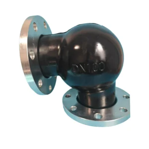
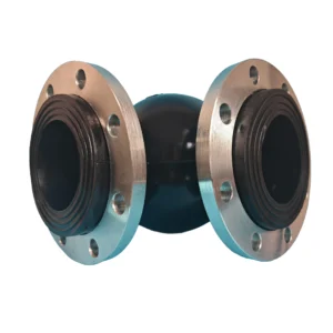
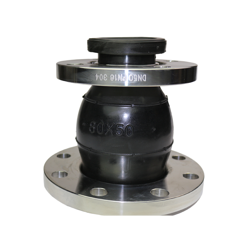
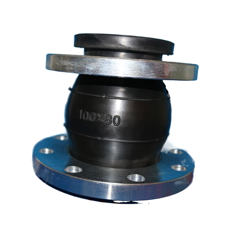
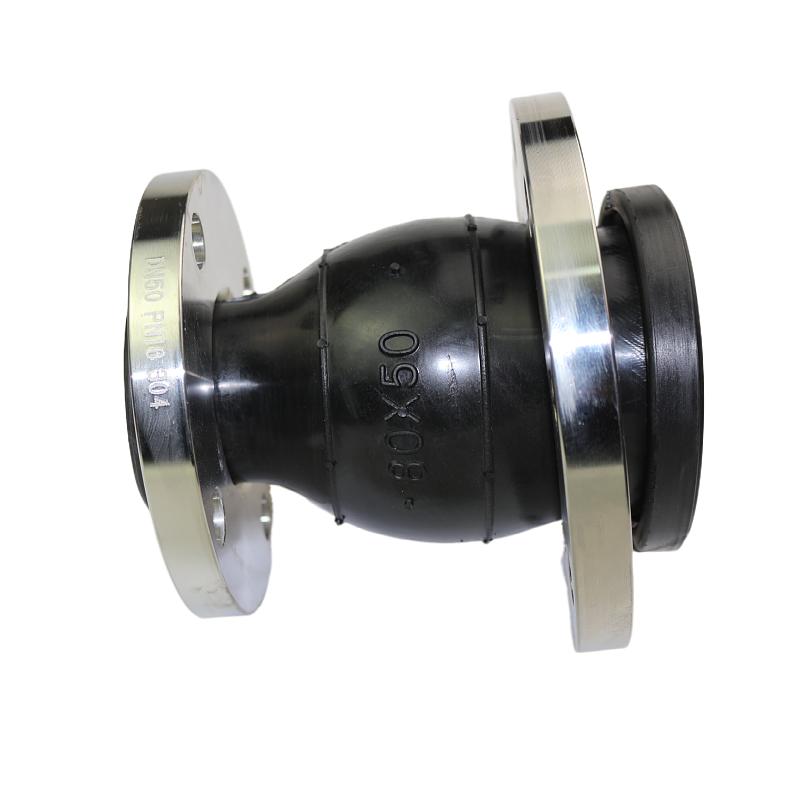
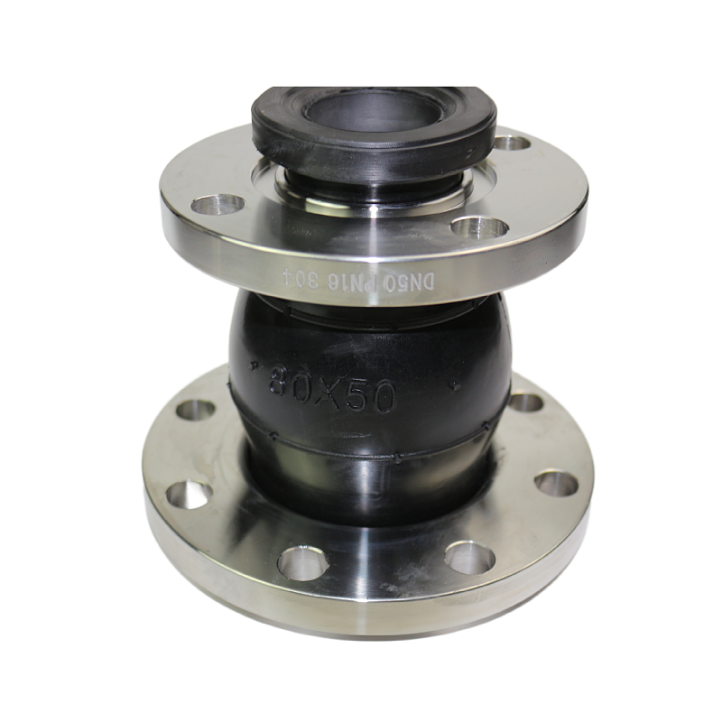
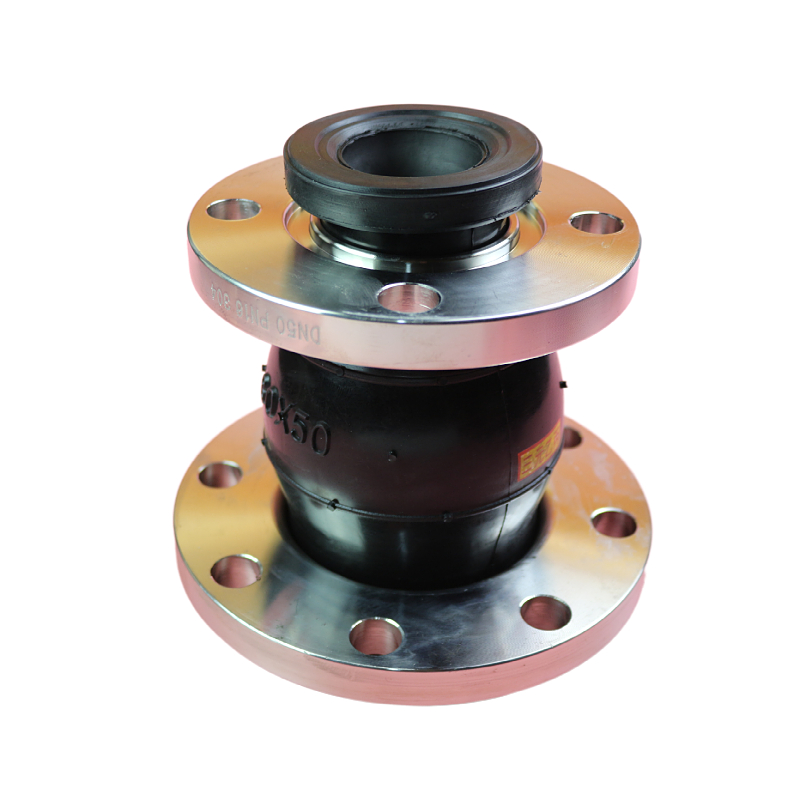
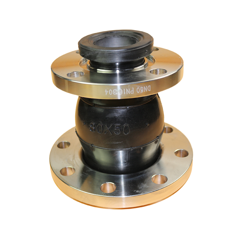
Hongze Reducing Rubber Expansion Joint is a flexible flanged connector used to join two pipelines with different nominal diameters. It combines pipe-size transition, vibration isolation and limited movement compensation in one compact component, reducing the need for a separate rigid reducer and equal-diameter rubber joint.
The reinforced rubber body helps absorb pump and equipment vibration, reduce structure-borne noise, compensate axial extension and compression, accommodate lateral displacement and angular deflection, and reduce mechanical loads transmitted to connected piping. The standard configuration has a concentric centerline. An eccentric reducing rubber expansion joint is available when the large and small pipe centerlines must be offset.
Each size must be specified as large-end DN × small-end DN, for example DN200 × DN150. A single DN value is not sufficient because both flange sizes, both drilling patterns, the reduction ratio and the flow direction affect the final design. Standard catalog combinations range from DN50 × DN32 to DN600 × DN500; other diameter pairs, lengths, rubber compounds and flange standards can be evaluated from drawings and operating data.
Key Features and Benefits
- Connects two different pipe diameters in one flexible component.
- Provides a compact alternative to a rigid reducer plus a separate rubber expansion joint.
- Absorbs vibration generated by pumps, compressors and rotating equipment.
- Helps reduce noise and vibration transmitted through rigid pipework.
- Compensates limited axial extension, axial compression, lateral displacement and angular deflection.
- Reduces mechanical stress transferred to pumps, valves, flanges and connected equipment.
- Standard concentric construction maintains a common centerline between different pipe sizes.
- Catalogued large-end × small-end combinations from DN50 × DN32 to DN600 × DN500.
- Available in EPDM, NBR, Natural Rubber, Neoprene and other application-specific compounds.
- Flange drilling and materials can be matched to ASME/ANSI, EN, DIN, JIS, BS, GB or project requirements.
- Carbon steel, galvanized steel, stainless steel 304 and stainless steel 316 flange options can be evaluated.
- Custom reduction ratios, installation lengths, reinforcement and control-unit arrangements are available after engineering review.
General Product Specifications
| Specification | Standard or Available Option |
|---|---|
| Product name | Reducing Rubber Expansion Joint |
| Alternative names | Concentric Reducing Rubber Expansion Joint, Rubber Reducer Joint, Flexible Rubber Reducer, Reducer Expansion Joint |
| Size designation | Large-end DN × small-end DN; both diameters are mandatory |
| Catalog size combinations | DN50 × DN32 through DN600 × DN500; see the complete table below |
| Standard geometry | Concentric reduction with a common centerline |
| Alternative geometry | Eccentric reduction with an offset centerline, ordered as a separate configuration |
| Connection | Flanged ends with independent large-end and small-end drilling |
| Movement | Axial extension, axial compression, lateral displacement and angular deflection |
| Rubber options | EPDM, NBR, Natural Rubber, Neoprene/CR, IIR or FKM/Viton according to service conditions |
| Reinforcement | Textile cord layers and reinforced end areas; construction depends on size and pressure |
| Flange materials | Carbon steel, galvanized carbon steel, stainless steel 304 or stainless steel 316 |
| Flange standards | ASME/ANSI, EN, DIN, JIS, BS, GB, HG or drawing-specific drilling |
| Pressure rating | Selected according to size pair, reduction ratio, rubber compound, temperature, flange rating and system conditions |
| Temperature range | Depends on rubber compound, medium, pressure and operating cycle; written confirmation is required |
| Typical media | Water, hot water, cooling water, air, seawater, oil and compatible industrial fluids |
| Customization | DN pair, length, concentric or eccentric geometry, rubber, reinforcement, flange, drilling, control units and marking |
Engineering note: Pressure, temperature, vacuum, movement, medium compatibility and service life are interdependent. The dimensional movement values below are catalog references, not permission to combine every maximum movement simultaneously. Final performance must follow the approved Hongze drawing and technical data sheet.
How the Size Is Specified
A reducing rubber expansion joint does not have only one DN size. The correct ordering format is:
Large-end nominal diameter × Small-end nominal diameter
Example: DN200 × DN150
| Information | Why It Matters | Example |
|---|---|---|
| Large-end DN | Defines the larger bore, flange outside diameter and drilling | DN200 |
| Small-end DN | Defines the smaller bore, flange outside diameter and drilling | DN150 |
| Flow direction | Large-to-small and small-to-large service produce different hydraulic behavior | DN200 → DN150 |
| Flange standard at each end | The two ends may have different bolt circles and pressure classes | EN PN16 × ASME Class 150 |
| Face-to-face length | Affects the reduction angle, flexibility and installation space | L = 200 mm |
| Concentric or eccentric | Defines whether both pipe centerlines coincide or are offset | Concentric |
When requesting a quotation, do not write only “DN200 rubber joint.” State both nominal diameters, the flow direction, flange standard at each end, working pressure, medium, temperature and required installation length.
Concentric vs. Eccentric Reducing Rubber Expansion Joint
| Comparison | Concentric Reducing Rubber Joint | Eccentric Reducing Rubber Joint |
|---|---|---|
| Centerline | Large and small ends share one centerline | Large and small ends have an offset centerline |
| Typical layout | Vertical piping and installations where centered transition is preferred | Horizontal piping where a flat-top or flat-bottom transition is required |
| Orientation | Normally rotationally symmetrical | Offset direction must be specified on the drawing |
| Pump piping | May be suitable when approved by the pump and piping design | Often considered where the system layout must reduce high points or low pockets; orientation requires engineering confirmation |
| Ordering information | Large DN × small DN, length and flange details | Large DN × small DN, length, flange details and eccentric direction |
| Product page | This page | View Eccentric Reducing Rubber Expansion Joint |
The correct geometry depends on the pipeline orientation, pump requirements, drainage, air management, solids content and available installation space. The piping or pump-system engineer should approve the reducer geometry and orientation.
Main Connection Dimensions and Movement
The table below preserves all 48 catalogued large-end DN × small-end DN combinations. Values are dimensional references for initial selection. Final dimensions, tolerances, pressure rating, drilling and allowable movements must be confirmed on the approved production drawing.
| Large End × Small End | Length L (mm) | Axial Extension (mm) | Axial Compression (mm) | Lateral Displacement (mm) | Deflection Angle |
|---|---|---|---|---|---|
| DN50 × DN32 | 180 | 20 | 30 | 45 | 35° |
| DN50 × DN40 | 180 | 20 | 30 | 45 | 35° |
| DN65 × DN40 | 180 | 20 | 30 | 45 | 35° |
| DN65 × DN50 | 180 | 20 | 30 | 45 | 35° |
| DN80 × DN40 | 180 | 20 | 30 | 45 | 35° |
| DN80 × DN50 | 180 | 20 | 30 | 45 | 35° |
| DN80 × DN65 | 180 | 20 | 30 | 45 | 35° |
| DN100 × DN40 | 180 | 20 | 30 | 45 | 35° |
| DN100 × DN50 | 180 | 20 | 30 | 45 | 35° |
| DN100 × DN65 | 180 | 22 | 30 | 45 | 35° |
| DN100 × DN80 | 180 | 22 | 30 | 45 | 35° |
| DN125 × DN50 | 200 | 22 | 30 | 45 | 35° |
| DN125 × DN65 | 200 | 22 | 30 | 45 | 35° |
| DN125 × DN80 | 200 | 22 | 30 | 45 | 35° |
| DN125 × DN100 | 200 | 22 | 30 | 45 | 35° |
| DN150 × DN50 | 200 | 22 | 30 | 45 | 35° |
| DN150 × DN65 | 200 | 22 | 30 | 45 | 35° |
| DN150 × DN80 | 200 | 22 | 30 | 45 | 35° |
| DN150 × DN100 | 200 | 22 | 30 | 45 | 35° |
| DN150 × DN125 | 200 | 22 | 30 | 45 | 35° |
| DN200 × DN80 | 200 | 22 | 30 | 40 | 30° |
| DN200 × DN100 | 200 | 22 | 30 | 40 | 30° |
| DN200 × DN125 | 200 | 25 | 30 | 40 | 30° |
| DN200 × DN150 | 200 | 25 | 35 | 40 | 30° |
| DN250 × DN125 | 220 | 25 | 35 | 40 | 30° |
| DN250 × DN150 | 220 | 25 | 35 | 40 | 30° |
| DN250 × DN200 | 220 | 25 | 35 | 40 | 30° |
| DN300 × DN125 | 220 | 25 | 35 | 40 | 30° |
| DN300 × DN150 | 220 | 25 | 35 | 40 | 30° |
| DN300 × DN200 | 220 | 25 | 35 | 40 | 30° |
| DN300 × DN250 | 220 | 25 | 35 | 40 | 30° |
| DN350 × DN150 | 240 | 25 | 35 | 40 | 30° |
| DN350 × DN200 | 240 | 28 | 38 | 35 | 26° |
| DN350 × DN250 | 240 | 28 | 38 | 35 | 26° |
| DN350 × DN300 | 240 | 25 | 35 | 40 | 30° |
| DN400 × DN200 | 240 | 25 | 35 | 40 | 30° |
| DN400 × DN250 | 240 | 28 | 38 | 40 | 30° |
| DN400 × DN300 | 240 | 28 | 38 | 40 | 30° |
| DN400 × DN350 | 240 | 28 | 38 | 40 | 30° |
| DN450 × DN300 | 240 | 28 | 38 | 40 | 30° |
| DN450 × DN350 | 240 | 28 | 38 | 40 | 30° |
| DN450 × DN400 | 240 | 28 | 38 | 40 | 30° |
| DN500 × DN350 | 240 | 28 | 38 | 40 | 30° |
| DN500 × DN400 | 240 | 28 | 38 | 40 | 30° |
| DN500 × DN450 | 240 | 28 | 38 | 40 | 30° |
| DN600 × DN400 | 240 | 28 | 38 | 40 | 30° |
| DN600 × DN450 | 240 | 28 | 38 | 40 | 30° |
| DN600 × DN500 | 240 | 28 | 38 | 40 | 30° |
Custom sizes: The table is not a list of every manufacturable combination. Other large-end and small-end diameters may be evaluated. A large reduction ratio, short face-to-face length, high flow velocity, vacuum, pressure surge or large diameter may require a longer body, different reinforcement, a special contour or a separate engineered reducer and expansion joint.
Rubber Material Selection
| Rubber Material | Typical Service | Main Characteristics | Important Limitation |
|---|---|---|---|
| EPDM | Water, hot water, cooling water, air, seawater and many water-based fluids | Good resistance to weather, ozone and many aqueous services | Generally unsuitable for petroleum oils and hydrocarbon fuels |
| NBR | Mineral oil, lubricating oil, fuel and oily water | Good resistance to many petroleum-based fluids | Exact oil composition, aromatic content and temperature must be checked |
| Natural Rubber | Water, air and non-aggressive general service | High elasticity, abrasion resistance and vibration absorption | Not normally selected for petroleum oil, strong chemicals or severe ozone exposure |
| Neoprene / CR | Weather-exposed service, seawater and selected industrial fluids | Balanced weathering and moderate oil resistance | Chemical and temperature compatibility must be confirmed |
| IIR | Selected gas, water and chemical services | Low gas permeability and good weather resistance | Not universally compatible with oils or every chemical |
| FKM / Viton | Selected higher-temperature, oil and chemical applications | Good heat and chemical resistance for compatible media | Compound-specific compatibility, flexibility and pressure limits require review |
Rubber selection must be based on the exact medium, concentration, minimum and maximum temperature, working pressure, cleaning chemicals and exposure time. A generic material name does not guarantee compatibility with every fluid.
Flange Standards and Materials
| Item | Available Options | Ordering Note |
|---|---|---|
| ASME / ANSI | Project-specified pressure class and drilling | State standard edition, class and facing |
| EN / DIN | PN-rated flange drilling | State EN or DIN reference, PN rating and facing |
| JIS | Project-specified K rating | State exact JIS standard and pressure designation |
| BS / GB / HG | Specified industrial or national flange drilling | Provide the complete standard number and pressure rating |
| Custom drilling | Manufactured from an approved drawing or flange sample | Provide bolt circle, hole quantity, hole diameter, outside diameter and facing |
| Flange material | Carbon steel, galvanized steel, stainless steel 304 or stainless steel 316 | State surface finish, corrosion requirement and material grade |
The large and small ends may require different flange standards or ratings. List the flange requirement separately for each end. Nominal DN and pressure class alone do not always define a complete flange.
Engineering and Flow Considerations
- Reduction ratio: A large difference between the two diameters creates a steeper transition and may require a longer body or special contour.
- Flow direction: Large-to-small flow increases velocity, while small-to-large flow can create expansion losses and flow separation. The system designer must confirm acceptable velocity, pressure drop and turbulence.
- Pump connections: The pump manufacturer and piping engineer should approve reducer geometry, orientation, straight-pipe length, supports and allowable nozzle loads.
- Vacuum service: Suction and vacuum conditions can require vacuum reinforcement. State the maximum vacuum and transient conditions before ordering.
- Solids and slurry: Abrasive particles and suspended solids can increase wear, especially at the transition. Provide particle size, concentration and flow velocity.
- Pressure surge: Water hammer, rapid valve closure and pump start/stop cycles must be included in the design pressure.
- Combined movement: Axial, lateral and angular values are not normally additive at their full catalog limits. Submit the actual movement combination.
- Thrust: Internal pressure generates end thrust. The pipe system requires correctly designed anchors, guides and supports.
Typical Applications
- Pump suction and discharge piping after engineering approval
- Water-supply and drainage systems
- HVAC chilled-water and heating-water pipelines
- Cooling-water and cooling-tower systems
- Municipal water and wastewater-treatment facilities
- Industrial process-water and utility piping
- Power-plant auxiliary piping
- Chemical pipelines with a compatible rubber compound
- Marine and seawater systems with suitable materials
- Equipment connections where pipe diameter changes near a vibration source
Reducing Rubber Joint vs. Rigid Reducer Plus Separate Rubber Joint
| Comparison | Reducing Rubber Expansion Joint | Rigid Reducer + Equal-Diameter Rubber Joint |
|---|---|---|
| Components | One integrated component | Two components plus an additional joint |
| Installation length | Normally more compact | Usually requires more straight-line space |
| Flanged connections | Two pipeline connections | Additional flange or welded connection may be required |
| Customization | Body must be manufactured for the exact DN pair | Standard components may be easier to source separately |
| Hydraulic design | Transition and flexible movement occur in one body | Reducer contour and flexible joint can be optimized separately |
| Extreme reduction ratio | May require special engineering or may not be recommended | A long rigid reducer may provide a more gradual transition |
| Maintenance | One custom flexible component to inspect | Separate standard parts can be inspected or replaced individually |
A reducing rubber expansion joint is useful when compactness and an integrated flexible transition are priorities. For high velocity, severe turbulence, extreme size reduction, demanding pump service or special process conditions, a separately engineered rigid reducer and standard rubber joint may be the better arrangement.
How to Select the Correct Reducing Rubber Expansion Joint
- State both sizes: Give the large-end DN and small-end DN in that order.
- State flow direction: Confirm whether flow travels from large to small or small to large.
- Choose the geometry: Confirm concentric or eccentric construction and, for eccentric construction, the offset direction.
- Identify the medium: Provide the fluid name, concentration, solids, oil content and cleaning chemicals.
- Provide temperature data: State minimum, normal and maximum operating temperatures.
- Provide pressure data: State working pressure, surge pressure, test pressure and maximum vacuum.
- Specify both flanges: Give standard, pressure class, facing, drilling and material for the large and small ends.
- Confirm face-to-face length: State available installation space and whether a catalog or custom length is required.
- Describe movement: Provide the calculated axial, lateral and angular movement, including frequency.
- Describe the piping system: Include pumps, valves, anchors, guides, supports, flow velocity and an installation sketch.
- State documentation requirements: Include inspection, test, marking, certificate, packaging and drawing requirements.
Installation Guidelines
- Verify the large-end and small-end sizes, flow direction, rubber compound, flange drilling and approved drawing before installation.
- Inspect the joint for transport damage, rubber cuts, flange deformation, contamination or corrosion.
- Ensure the mating flanges are aligned, parallel and at the correct face-to-face distance. Do not use the joint to pull misaligned pipework into position.
- Install the correct end toward each pipeline size. Confirm the required flow direction and any eccentric orientation.
- Support the adjoining pipework independently. Do not allow pipe, valve or equipment weight to hang from the rubber body.
- Insert bolts carefully so that threads and bolt ends cannot cut or abrade the rubber arch.
- Tighten flange bolts gradually in a cross pattern using controlled, even passes. Follow the approved bolt and flange instructions.
- Do not twist, over-compress, over-extend or laterally offset the joint during installation.
- Keep welding heat, sparks, paint, insulation chemicals, petroleum grease and sharp tools away from the rubber.
- Install anchors, guides, supports and control units where required by the system design.
- After installation, inspect alignment and bolt tightness, then perform the specified pressure or leak test under controlled conditions.
Anchors, Guides and Control Units
Internal pressure creates thrust at the change in pipe area and at the flexible joint. A reducing rubber expansion joint must not be treated as a self-anchoring pipe restraint. The piping system must use correctly designed anchors, guides and supports to carry pressure thrust and equipment loads.
For large diameters, high pressure, high-rise service, suspended piping, unanchored systems or service near pumps and valves, an engineered control-unit arrangement may be required. Control rods or tie rods limit excessive movement; they do not replace properly designed anchors, guides and supports and do not correct pipe misalignment.
Inspection and Maintenance
- Inspect the rubber body for cracking, blistering, cuts, abrasion, softening, hardening or abnormal bulging.
- Check for leakage, flange corrosion, loose fasteners and uneven gasket compression.
- Confirm that the joint remains within its installed movement and alignment limits.
- Inspect anchors, guides, supports and control units for movement, corrosion or looseness.
- Investigate changes in vibration, noise, temperature, pressure or process medium.
- Replace the joint if reinforcement is exposed, the rubber is chemically attacked, leakage occurs or deformation exceeds the approved limit.
- Set inspection intervals according to service severity, pressure, temperature, movement cycles and plant safety procedures.
Custom Manufacturing
Zhengzhou Hongze Valve & Pipeline Equipment Co., Ltd. can evaluate custom reducing rubber expansion joints according to project drawings and operating data. Available engineering options include:
- Non-catalog large-end DN × small-end DN combinations
- Custom face-to-face length and reduction contour
- Concentric or eccentric geometry
- EPDM, NBR, Natural Rubber, Neoprene, IIR or FKM/Viton compounds
- Different flange standards or pressure classes at each end
- Carbon steel, galvanized steel, stainless steel 304 or stainless steel 316 flanges
- Special drilling based on an approved flange drawing
- Additional reinforcement for reviewed pressure or vacuum conditions
- Control rods, tie rods or other engineered movement-limiting arrangements
- Project marking, inspection, packaging and documentation
Why Choose Hongze
- Engineering review based on both pipe diameters, not a single DN value.
- Support for rubber compatibility, flow direction, flange standard, pressure and length selection.
- Standard and custom reducing combinations for industrial pipeline projects.
- Concentric and eccentric solutions for different pipe layouts.
- Custom flange drilling and material options for international projects.
- Production drawings can be confirmed before manufacturing.
- Direct technical communication for drawings, quotations and project-specific requirements.
Frequently Asked Questions
What is a reducing rubber expansion joint?
It is a flexible connector that joins two different pipe diameters while providing vibration isolation and limited axial, lateral and angular movement compensation.
Does the product have only one DN size?
No. It must be identified by two sizes: the large-end DN × small-end DN. For example, DN200 × DN150 means one end fits a DN200 pipeline and the other fits a DN150 pipeline.
What is the difference between concentric and eccentric reducing rubber joints?
A concentric joint keeps both pipe centerlines aligned. An eccentric joint offsets the centerlines so one side can remain flat. The piping layout, pump requirements, drainage and air management determine the correct choice.
Can the flow travel in either direction?
The joint can be manufactured for either direction, but large-to-small and small-to-large flow have different effects on velocity, pressure loss and turbulence. State the intended flow direction so the application can be reviewed.
Are sizes outside the catalog table available?
Other diameter combinations may be manufactured after engineering review. Provide both DN sizes, length, pressure, medium, temperature, flange details and an installation drawing.
Which rubber is suitable for water service?
EPDM is commonly selected for water, hot water and many water-based services. The exact compound must still be checked against temperature, pressure, water treatment chemicals and operating cycle.
Which rubber is suitable for oil?
NBR is commonly selected for many petroleum-oil applications. Provide the exact oil, additives, aromatic content and temperature because compatibility varies by formulation.
Can the two ends use different flange standards?
Yes, a transition joint can be evaluated with different drilling requirements at the large and small ends. State the complete standard, class or PN rating, facing and material for each end.
Can the catalog movement values be used at the same time?
Not automatically. Axial, lateral and angular movements interact, so the full catalog maximum in every direction should not be combined unless the approved technical data explicitly permits it.
Does the joint eliminate the need for pipe anchors?
No. The system still requires correctly designed anchors, guides and supports. Control rods can limit excessive movement but are not a substitute for proper piping restraint and alignment.
When is a separate rigid reducer and rubber joint preferable?
A separate arrangement may be preferable for extreme reduction ratios, high flow velocity, severe turbulence, demanding pump service or when the reducer contour and flexible movement must be engineered independently.
What information is required for a quotation?
Please send the large-end DN, small-end DN, flow direction, concentric or eccentric geometry, medium, temperature, working and surge pressure, vacuum, flange standard at both ends, face-to-face length, movement, quantity and a pipeline drawing.
Related Products
- Eccentric Reducing Rubber Expansion Joint
- Single Sphere Rubber Expansion Joint
- All Rubber Expansion Joints
Request a Technical Quotation
Send both DN sizes, flow direction, working medium, temperature, pressure, flange standards, installation length, quantity and drawings. Hongze will review the reduction ratio, rubber compound, flange configuration and movement requirements before quotation.
WhatsApp: +86 15838027988
Email: export@hongzepipe.com
Contact: Send Your Project Requirements